Voltage Divider Formula and Calculator (5 V to 3.3 V Example)
Voltage divider formula Vout = Vin × R2 ÷ (R1 + R2), resistor pairs for 5 V to 3.3 V, sensors like LDRs, and a free calculator.
ON THIS PAGE
Two resistors in a row can turn a bigger voltage into a smaller one. This little circuit — the voltage divider — is how an Arduino reads a light sensor, how a 5 V signal is made safe for a 3.3 V ESP32, and how a multimeter measures high voltages.
Free voltage divider calculator
Slide R1 and R2 and watch the output voltage. Try the presets: half, 5 V → 3.3 V, and 9 V → 5 V.
⚡ LOADING THE CALCULATOR…
Free, no sign-up. Prefer a bigger screen? Open the Voltage divider calculator in the Lab →
How a voltage divider works
The same current flows through both resistors (they are in series). By Ohm's law, each resistor "takes" a share of the voltage in proportion to its resistance. The output is the voltage across the bottom resistor, R2.
Example
Vin = 9 V, R1 = 4.7 kΩ, R2 = 5.6 kΩ: Vout = 9 × 5,600 ÷ 10,300 = 4.89 V.
A quick way to think about it: bigger R2 → more of the voltage at the output.
Popular resistor pairs
| Goal | R1 (top) | R2 (bottom) | Vout |
|---|---|---|---|
| Half of the input | 10 kΩ | 10 kΩ | Vin ÷ 2 |
| 5 V → 3.3 V (signal) | 1.8 kΩ | 3.3 kΩ | 3.24 V |
| 5 V → 3.3 V (signal) | 1 kΩ | 2 kΩ (or 2.2 kΩ) | 3.33 V (3.44 V) |
| 5 V → 3.3 V (low current) | 10 kΩ | 20 kΩ | 3.33 V |
| 12 V battery → under 5 V for analogRead | 22 kΩ | 10 kΩ | 3.75 V (from 12 V) |
| 9 V → ≈ 5 V | 4.7 kΩ | 5.6 kΩ | 4.89 V |
Using a divider to read sensors
Replace R2 (or R1) with a sensor whose resistance changes:
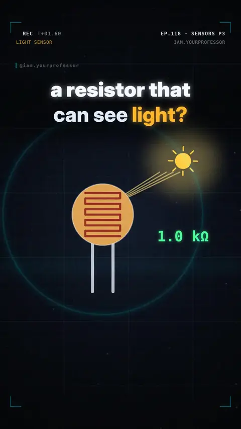
- LDR (light sensor): its resistance drops in bright light, so Vout moves with the light. An Arduino reads it with
analogRead(A0)(0–1023 for 0–5 V). - NTC thermistor: resistance drops as it warms up → a temperature reading.
- Potentiometer: a divider with a slider — turn the knob and Vout goes from 0 to Vin.
Pick the fixed resistor close to the sensor's resistance in the middle of the range you care about; that gives the biggest change in Vout.
Why a voltage divider can't power things
A divider is for signals, not power. Connect a load (a motor, an LED strip, a board) to Vout and it acts like a third resistor in parallel with R2 — the output voltage drops. It also wastes power as heat all the time.
To get a steady lower supply voltage, use a voltage regulator (like a 7805 or an AMS1117-3.3) or a buck converter instead.
5 V to 3.3 V logic: divider or level shifter?
- 5 V Arduino output → 3.3 V ESP32 / Pico input: a divider (1.8 kΩ / 3.3 kΩ) works well for slow signals like UART at normal speeds.
- 3.3 V output → 5 V input: usually no divider needed — most 5 V boards read 3.3 V as HIGH. Check the datasheet.
- Fast or two-way signals (I²C): use a proper level shifter module.
Frequently asked questions
What is the voltage divider formula?
Vout = Vin × R2 ÷ (R1 + R2), where R2 is the resistor connected to ground and Vout is measured across it.
What resistors do I need to convert 5V to 3.3V?
A 1.8 kΩ top resistor and a 3.3 kΩ bottom resistor give about 3.24 V. 1 kΩ and 2 kΩ give 3.33 V. This is for signals only, not for powering a board.
Can I use a voltage divider to power a device?
No. The load pulls the output voltage down and the resistors waste power. Use a voltage regulator or a buck converter.
Why is a voltage divider used with an LDR?
An Arduino can measure voltage but not resistance. The divider turns the LDR's changing resistance into a changing voltage that analogRead can read.