Embedded C Part 6: What is a register?
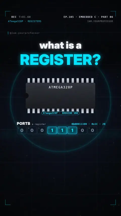
DDRB / PORTB / PINB: 8 switches each — direction, output, input — that control port B's pins.
What is a register, really? 🤔 It's the secret behind every pin of your Arduino 👇
1️⃣ 8 TINY SWITCHES: a register is a row of 8 bits — 8 tiny switches — inside the ATmega328P chip. On port B, each bit controls one pin: PB0 = D8 … PB5 = D13 (PB6 and PB7 run the crystal on the Uno).
2️⃣ DDRB + PORTB: DDRB sets the direction (1 = output). PORTB sets the level (1 = HIGH, 5 V).DDRB = 0b00100000;PORTB = 0b00100000;
→ pin D13's LED turns on.
3️⃣ PINB: reads what each pin really sees. Bit 5 = PB5 = pin D13 = the on-board LED.
Direction, output, input — 3 registers per port!
Try it: paste the code into the Arduino IDE (a sketch with its own int main) or a free online Uno simulator.
// EC L06 - three registers control every pin of port B
#include <avr/io.h>

int main(void) {
    DDRB  = 0b00100000;  // Direction: 1 = output (PB5 = D13)
    PORTB = 0b00100000;  // Output   : 1 = HIGH (5 V)
    uint8_t now = PINB;  // Input    : read real pin levels
    (void)now;
    while (1) { }
}
Read the voiceover (transcript)
- What is a register, really?
- It's a row of eight tiny switches inside the chip. Each bit controls one pin!
- D D R B sets direction: one is output. Port B sets the level: one is five volts.
- And pin B reads what each pin really sees. Bit five is pin thirteen, the LED!
- Direction, output, input!
- Next: LED on with two lines! Follow for part seven!
Related lessons
Get new lessons + early access to the full course
One email when new lessons drop. No spam, unsubscribe any time.
✓ You're on the list! We'll email you when new lessons drop.
By joining you agree to the privacy policy.